The estimator was then tested on image sequences of 3-D scenes
consisting of textured surfaces moving with respect to a stationary
camera. The geometry was similar to that used in the first experiment
and the surfaces were translated in the xy-plane and rotated about
the three axes. Three surfaces were experimented with as shown in
Figs. 5 - a plane (a), a Gaussian (b) and a
saddle surface (c) - and a tree bark image was texture
mapped onto each to generate sequences consisting of frames of size
![]() pixels. Sixteen
pixels. Sixteen ![]() pixel regions were then
selected by hand and tracked through each sequence using the evolving
Gaussian windows as described in Section
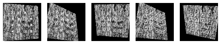
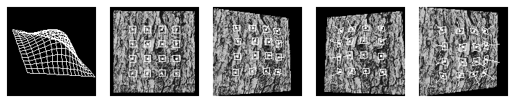
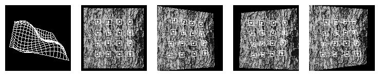
3. Figure 5 shows the
structure estimates from the filter overlaid on the corresponding
frames, where the depths and surface normals are represented by
perspective projections of oriented `platelets' with needles
indicating the normal direction. The top left image shows the initial
state (normals pointing towards the camera and arbitrary depth values)
and the centre and right column shows the state of the platelets at a
frame further on in the sequence. The filter captures
the surface structure well in each case, showing clearly the variation
in depth and surface normal (this is better appreciated when viewing
the sequences). Motion and inverse focal length estimates also
converge quickly as shown in Fig. 6.
The image sequence for the Gaussian surface is also available as an mpeg movie.
pixel regions were then
selected by hand and tracked through each sequence using the evolving
Gaussian windows as described in Section
3. Figure 5 shows the
structure estimates from the filter overlaid on the corresponding
frames, where the depths and surface normals are represented by
perspective projections of oriented `platelets' with needles
indicating the normal direction. The top left image shows the initial
state (normals pointing towards the camera and arbitrary depth values)
and the centre and right column shows the state of the platelets at a
frame further on in the sequence. The filter captures
the surface structure well in each case, showing clearly the variation
in depth and surface normal (this is better appreciated when viewing
the sequences). Motion and inverse focal length estimates also
converge quickly as shown in Fig. 6.
The image sequence for the Gaussian surface is also available as an mpeg movie.
Figure 5a: Texture mapped `Plane' surface with overlaid `platelets'
indicating the estimated surface normals and depths.
Figure 5b: Texture mapped `Gaussian' surface with overlaid `platelets'
indicating the estimated surface normals and depths.
Figure 5c: Texture mapped `Saddle' surface with overlaid `platelets'
indicating the estimated surface normals and depths.
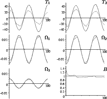
Figure 6: Motion and inverse
focal length estimates compared with the known groundtruth (dark
lines) for the texture mapped plane.